 |
| May 26, 2015 | Volume 11 Issue 20 |
Designfax weekly eMagazine

Archives
Partners
Manufacturing Center
Product Spotlight
Modern Applications News
Metalworking Ideas For
Today's Job Shops
Tooling and Production
Strategies for large
metalworking plants
Understanding actuators through simulation
Multiphysics system simulation provides insight into the operations of actuators.
By Mark Solveson, Application Engineer, ANSYS, Inc.
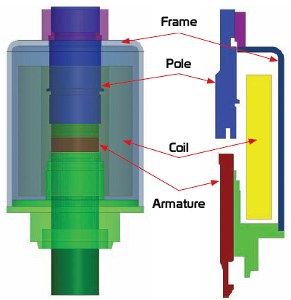
Three-dimensional and axis-symmetric view of typical electromagnetic actuator, with frame, pole piece, coil, and armature defined.
Electromagnetic actuators, or solenoids, are devices that operate by producing magnetic fields to move an armature a desired distance at a desired force. They are used in applications such as fuel injectors, power distribution (interrupters and breakers, for example), and various automotive, hydraulic, and industrial applications.
A typical electromagnetic actuator consists of a multiturn coil configured around a ferrous pole and a moveable armature. Additional ferrous parts, such as a frame, provide a return path for the magnetic flux. When the actuator is connected to a voltage source, current flows through the coil and creates magnetic flux in the device, and, as a result, magnetic force is produced that moves the armature from open to closed position. Other actuator configurations may include permanent magnets to assist in flux production or to help hold the armature in place while voltage is switched off in the coil. Voice coil actuators use permanent magnets to produce a magnetic flux that impinges the coil current and, thus, produces a Lorentz force on the coil. These devices may be 2D or 3D in nature and can include rotational motion or noncylindrical rotation (rocker motion).
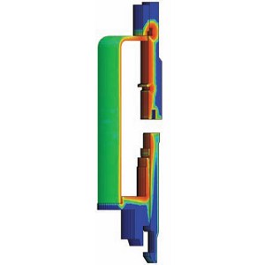
Magnetic flux density shown during a transient simulation after 0.001 sec. Figure shows detail of magnetic diffusion due to eddy currents. As time progresses, the fields diffuse through the thickness of the device, the force increases, and the armature closes once the magnetic force overcomes spring and load forces.
The ferrous material of the armature, pole, and frame is modeled with nonlinear BH curves to capture important saturation effects that can limit performance. The size and shape of the armature and mating pole affect the force profile on the armature and/or the closing time. Additionally, the design of the coil determines electrical resistance and strongly affects coil inductance, since the inductance is equal to the square of the number of coil turns multiplied by the total magnetic permeance of nonlinear ferrous objects and air gaps. The ratio of the inductance divided by the resistance (L/R) is the electrical time constant; it determines how fast current can rise in the coil. Considering this rise time of current due to the electrical time constant, the magnetic diffusion time (how fast the magnetic flux builds up in the device due to eddy currents) can also affect actuator performance. During a fast rise in current, the magnetic flux is crowded near the inner surface of the actuator before diffusing through the device, thus delaying the buildup of force on the armature. Similarly, magnetic effusion occurs when the voltage is switched off and magnetic flux dissipates out of the device, which can delay the opening of the armature.
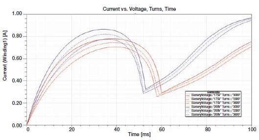
Parametric sweep of a current transient versus coil turns and voltage are distributed over several CPUs to reduce total simulation time.
Two- and three-dimensional magnetic analyses can be performed using the static or transient solvers in Maxwell electromagnetic field simulation software. Often, the coil design (shape factor, number of turns, and wire size) and geometry optimization can be done in a series of static simulations in which the current and position are varied to produce a family of curves representing armature force versus position and current. Since Maxwell uses automatic adaptive meshing for each of these variations, it is very easy to perform parametric sweeps or optimizations on these variables. Beyond the static simulation approach, full electrical and mechanical transients using the Maxwell transient solver can be considered to determine how fast the armature reaches the closed position. A robust simulation of this type can be completed using an arbitrarily defined voltage source (or attached circuit using the Maxwell circuit editor), nonlinear materials, and mechanical equations of motion (including damping and load forces, which can be functions of position, speed, or time), in which eddy currents and magnetic diffusion are considered. Parametric sweeps, design of experiments, or optimization of static or transient cases can be automatically distributed on a cluster of computers or CPUs to reduce total solution time.
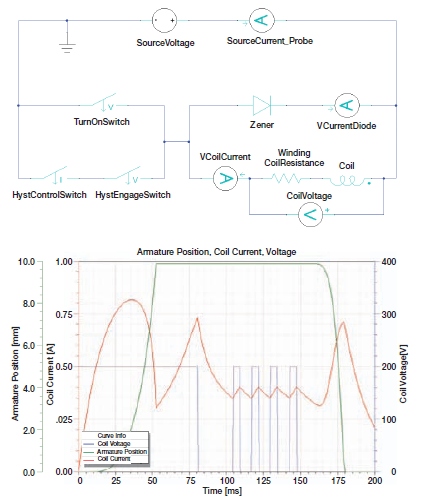
Created using the circuit editor within Maxwell, a transient simulation with a chopped current controller shows transient waveforms of position, coil current, and coil voltage.
If a more detailed electronic circuit is required, then Simplorer may be used to cosimulate with Maxwell. Simplorer software is a multi-domain circuit and system simulation tool that models circuits, block diagrams, state machines, and VHDL-AMS components. It also dynamically couples to several other simulation tools from ANSYS.
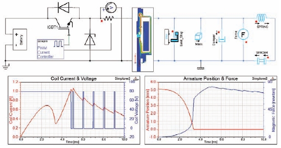
Robust system simulation in Simplorer shows a drive circuit coupled to the Maxwell FEA model through a coupled transient link. Mechanical pins are connected to define mass, forces, springs, and limit stops. Plots show coil current and voltage along with armature position and force versus time.
Alternatively, Simplorer software can use an equivalent circuit generated from a parametric sweep of position and coil current (in which eddy effects are ignored). Detailed semiconductor models and closed-loop control systems can be used with a detailed 2D or 3D actuator model that can be connected to a mechanical/hydraulic load using the available multidomain components in Simplorer.
Once the time domain coil and core losses are determined in the electromagnetic models, they can be mapped to ANSYS Mechanical software or ANSYS CFD (fluid dynamics) products for thermal analysis within the ANSYS Workbench environment. The time-averaged losses are spatially mapped to the thermal models, in which heat transfer coefficients are assigned or solved explicitly using ANSYS CFD. The steady-state temperature of the actuator is evaluated along with transient thermal performance and thermal cycling.
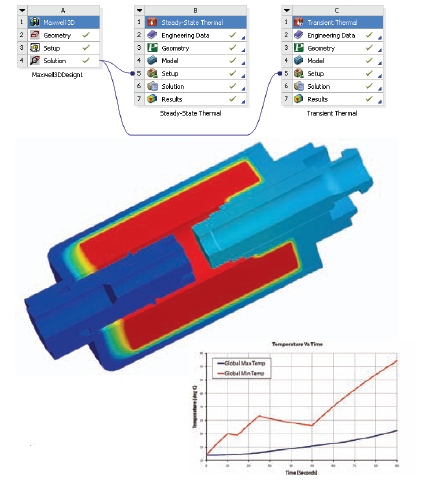
ANSYS Workbench enables mapping of the losses from a magnetic simulation to a static and/or transient thermal simulation.
ANSYS provides a comprehensive analysis approach for electromagnetic actuators. Whether the application is static, transient, thermal, or system analysis, there is an integrated tool set available to cover any level of analysis.
Want more information? Go to www.ansys.com.
Published May 2015
Rate this article
View our terms of use and privacy policy